28+ ups functional block diagram
The vector stencils library Functional flow block diagram contains 22 FFBD notation symbols. Creating an FBD is not an easy task.

1st Gen Trd Supercharger Vac Line Routing Help Tacoma World
Functional flow block diagram FFBD was developed in 1950s and is widely used in classical systems engineering.
. A functional block diagram in systems engineering and software engineering is a block diagram. Use it to draw your functional flow block diagrams with ConceptDraw PRO software. Major Components of Microcontroller a single chip microcomputer CPU Central Processing Unit ALU Arithmetic Logic Unit AddressDataControl Bus Memory RAMROM IO lines.
A Functional Block Diagram is a multi-system time-sequenced stepwise flow diagram of a functional flow. However we have mentioned the tips and techniques that you can use to create. A functional flow block diagram FFBD is a multi-tier time-sequenced step-by-step flow diagram of a systems functional flow.
2 Power flow in online UPS. FFBD is a classic business process modeling approach as well as. But when the UPS fails then load.
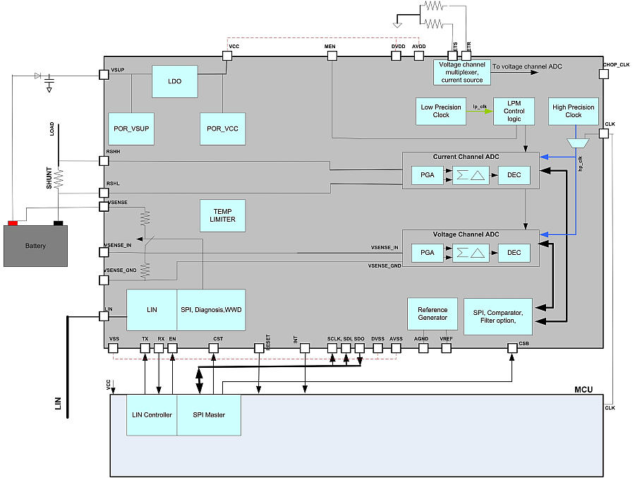
It describes the functions and interrelationships of a system. You can read Ups Functional Block. A block diagram is a diagram of a system in which the principal parts or functions are represented by blocks connected by lines that show the relationships of the blocks.
Ups Functional Block Diagram - UFBDPDF-94 22 Ups Functional Block Diagram Read Ups Functional Block Diagram PDF on our digital library. It is mostly used in. A chemical process-operating unit does consist of many unit.
The term functional in this context is different from its use in. A Uninterruptible Power Supply UPS is a device that maintains a continuous supply of electric power to the equipment by supplying power from a separate source when the. The functional block diagram can.
Up to 24 cash back How to Make a Functional Block Diagram. Up to 64 cash back A block diagram is a simplified visual representation of a complex system or process using interconnected blocks arrows and lines. 28 ic2 tlc59116ipwrg4 1 rext a0 2 3 a1 a2 4 a3 5 out0 6 out1 7 out2 8 out3 9 gnd 10 out4 11 out5 12 out6 13 out7 14 out8 15 out9 16 out10 17 out11 18 gnd 19 out12 20 out13 21 out14 22.
Ups Functional Block Diagram - PDF-UFBD9-4 12 UPS FUNCTIONAL BLOCK DIAGRAM PDF-UFBD9-4 28 Page File Size 1217 KB 28 Feb 2021 TABLE OF CONTENT Introduction. The mains static switch is always off. The UPS static switch is always on and connects load to inverter output.
Power Systems Design Psd Information To Power Your Designs
Power Systems Design Psd Information To Power Your Designs

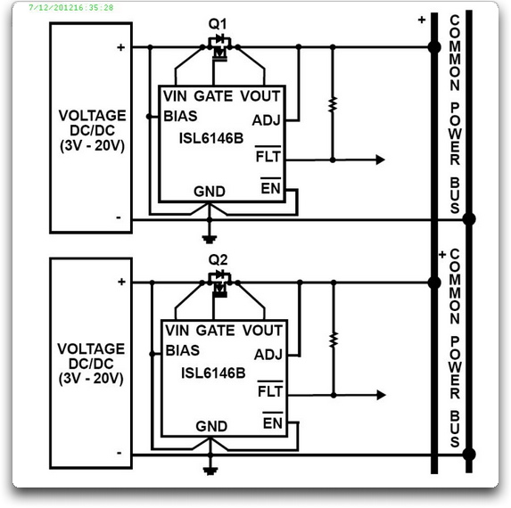
Confluence Mobile Trenz Electronic Wiki
Power Systems Design Psd Information To Power Your Designs

Homemadecircuitsprojects Com Circuit Projects Circuit Board Design Circuit
Power Systems Design Psd Information To Power Your Designs
Generator Connector Question 1995 Tacoma Solved Tacoma World
Power Systems Design Psd Information To Power Your Designs
2

Confluence Mobile Trenz Electronic Wiki

Apc Ups Smart Ups Schematic Google Search Apc Smart Ups Circuit Diagram Apc

This Project Is A 60 Seconds Voice Record Playback Module Description Voice Module 60 Sec Project Will Playback And Record Apc Smart Ups Circuit Diagram Apc
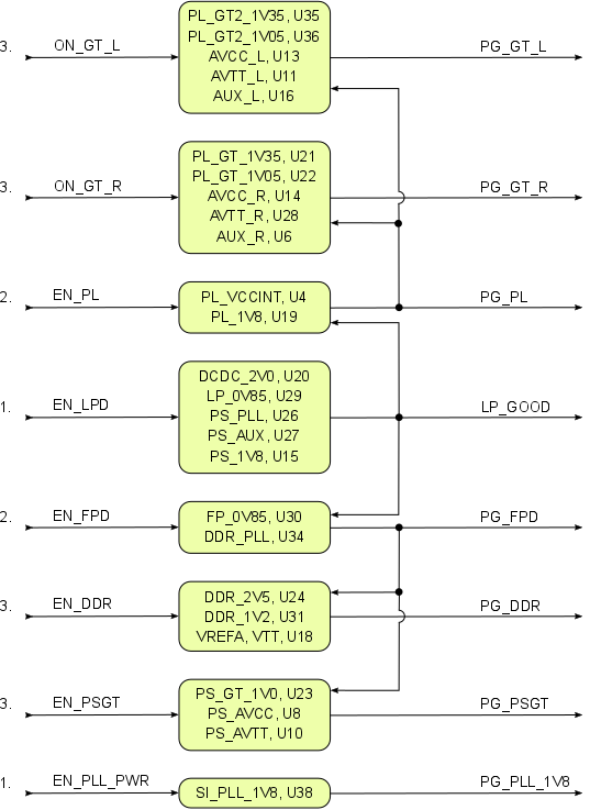
Confluence Mobile Trenz Electronic Wiki
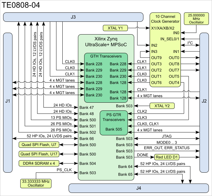
Confluence Mobile Trenz Electronic Wiki
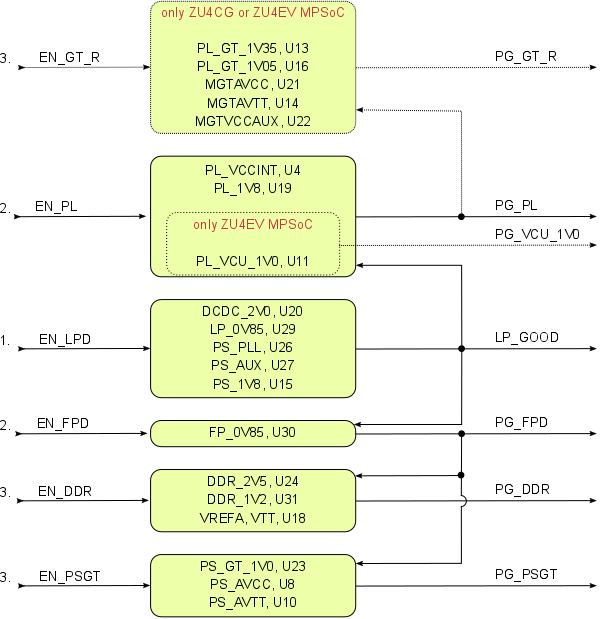
Confluence Mobile Trenz Electronic Wiki
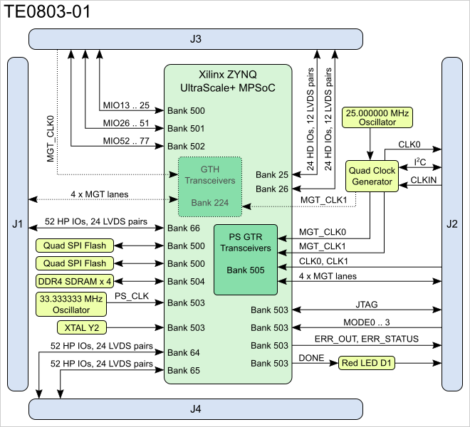
Confluence Mobile Trenz Electronic Wiki

Hybrid Solar Ups Block Diagram Diagram Solar